How to Define the Required Sensing Area for Pressure Mapping
Define coverage from the real contact interface before selecting a sensor family. The active area must include the contact region and credible variation, while the complete sensor still has to fit the fixture and route its tail safely.
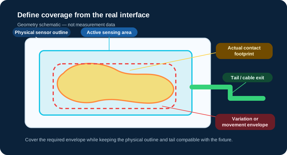
Define the required sensing area by mapping the full contact footprint and then adding only the credible region created by positioning variation, fixture tolerances or movement during the test. Check that this active area fits inside a physical sensor outline that can enter the interface and route its tail without interfering with loading. Coverage and spatial resolution are separate decisions, and final sensor, reader and software configuration should be confirmed for the application.
Start with the actual contact footprint
The first boundary is the region where contact can really occur—not the overall size of the part and not the available space in the fixture. Use a drawing, a controlled imprint, prior interface evidence or a measured physical outline to identify the surface that must be observed. Mark openings, cut-outs, fasteners and zones that cannot carry contact so they are not mistaken for required measurement coverage.
Define what the engineering decision needs to include. A test that compares two central contact regions may need a different area from a test that must check edge loading across the complete interface. The selected area should cover the evidence needed for that decision without assuming that more area automatically produces a better result.
Account for position variation and possible movement
A single nominal drawing may not describe every test position. Consider part-to-part locating variation, assembly tolerance, fixture play, operator placement and the way load can shift contact during compression. The useful envelope is the union of credible contact positions under the intended test—not an arbitrary margin applied to every side.
| Source of variation | Question to answer | Coverage implication |
|---|---|---|
| Part location | Can the part sit in more than one repeatable position? | Include the defined location tolerance where contact may occur. |
| Fixture tolerance | Can guides, clamps or platens move the interface relative to the sensor? | Use the credible fixture envelope, not a universal allowance. |
| Load-induced shift | Can compression, tilt or compliance move the contact zone? | Cover the shifted region that matters to the test objective. |
| Moving contact | Does contact travel across the surface during recording? | Define the complete observable path and confirm the acquisition method. |
Distinguish active sensing area from the physical sensor footprint
Active sensing area is the region containing the sensing matrix. Overall sensor footprint includes inactive borders, conductors, transition areas and the tail or connector region. A sensor can provide enough active coverage yet still be impossible to install because its border contacts a fixture feature or its tail cannot leave the interface.
Review both sets of geometry on the same interface drawing. Confirm where the active matrix begins and ends, where the physical edge sits, and which direction the tail exits. If the interface has an obstruction or a narrow entry path, overall geometry may become the limiting factor before active area.
Check insertion, edge coverage and tail routing
Sensor placement adds a physical layer to the tested interface. Decide how the array will be inserted, aligned and held without creasing or pinching it. Record whether the fixture can open far enough, whether the sensor must pass an edge or fastener, and whether an alignment reference can be used consistently.
- Keep the active region aligned with a repeatable interface reference.
- Confirm whether edge contact must be measured or deliberately excluded.
- Keep the transition and tail away from concentrated loading where the configuration permits.
- Provide an unobstructed exit path that does not force a sharp fold or cross a moving component.
- Document any protective layer, carrier or placement aid because it can affect the tested arrangement.
Sensing area and spatial resolution are different decisions
Sensing area answers where contact must be covered. Spatial resolution, pitch and matrix arrangement answer how finely the covered area is represented. A large active area can still have insufficient spatial detail for a small feature, while a fine matrix can miss the decision region if its coverage is too small.
Set the coverage boundary first, then describe the smallest contact feature or distribution change that matters. Matrix, pitch and sensing-point selection requires its own configuration review; this page does not prescribe a universal point count or pitch and does not replace that separate decision.
Separate static coverage from a moving contact envelope
For a sustained or slowly changing contact, the required area may be based on the maximum stable footprint plus credible position shift. For moving contact, the array may need to cover the complete travel path that must be observed. Motion also affects fixation, recording time and data acquisition, so a geometry decision alone cannot confirm that the event can be captured.
If contact enters or leaves the active area, define whether the transition itself is important. A larger area is not automatically the answer: the sensor construction, reader, matrix and acquisition workflow still need to support the intended event.
Sensing-area selection checklist
- Identify the actual interface where contact occurs.
- Mark the nominal contact footprint and any excluded zones.
- Define the engineering decision and the edges or regions it requires.
- Record part-position and fixture tolerances that can move the footprint.
- Describe load-induced shift or a moving contact path.
- Draw the maximum credible contact envelope.
- Check active sensing-area coverage against that envelope.
- Check the complete sensor outline against fixture access and obstructions.
- Define insertion direction, alignment reference and tail exit.
- Describe the smallest spatial feature that must be distinguished as a separate selection input.
Information to provide for application review
Provide a dimensioned interface drawing or clear top-view sketch, the nominal contact footprint, expected variation or movement, fixture opening and obstructions, insertion direction, tail-routing space, surface shape, loading method, static or moving event description, and the result the test must support. Photographs can help explain access, but dimensions and test conditions should remain the basis of configuration review.
Related products and resources
Review the measurement interface
Share the contact footprint, expected variation, fixture access and test objective for application-focused configuration review.
Review application evaluation